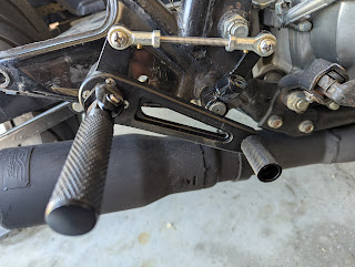
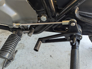
The desire to put rearsets on my cb750c has been kicking around in my head for many years. I've always felt my short legs didn't feel comfortable with the cruiser style ergonomics of the original foot peg placement but I didn't know how to mount rearsets.
Roughly 3 years ago, I found a set that I liked and ordered them though I still had no idea how to mount them without spending the money for the cognito moto brackets. I'm sure I'll end up spending some money for one of their fine products but they just seem too spendy for me, so I kept that option as a fallback in case I couldn't figure a way out. The rearsets sat in my garage but nothing came to me. At some point, I even bought some old brackets for a cb750f but didn't have an appropriate bolt to make that work. My swing arm swap bolt modification kinda caused an issue with mounting the part, but I don't remember the details around it now.
The easy and lazy solution was always to use the rear passenger foot peg mount and then convince myself and anyone that asks that I prefer that position but I'm old and there's no way I could see myself getting my foot back that far for very long without some-kind of cramp making getting home difficult.
After learning to design in Tinker CAD and also how to print advanced engineering grade filaments such as PA6-CF, I started to work towards designing a mount for the rearset closer to where the cognito moto brackets position the foot pegs. I'm using the thin wall in the triangle that protrudes from the frame for the rear foot pegs as the base for the mount. Recognizing the thin flexible walls, I have part of my 3d printed mount sitting on the lower tube support for the triangle but there's definitely some flex in the foot peg when I put weight on them.
Some design considerations that I'm aware of and have not dismissed:
- The thin metal is not strong enough to mount the pegs
- The carbon fiber filament will exhibit creep and/or might fail catastrophically as it ages
- The printed parts will absorb moisture from humid summer weather and turn mushy
I hope to either redesign the base mounting brackets or recreate them in metal in the future but need to use the next few riding seasons for field testing my proof of concept.

|
| Old Brake Lever Modified |

|
|||
| Old Shift Lever Modified |
Rather than cut my foot controls, I purchased a used set on eBay in the event I need to revert the modifications.
I welded the extensions I needed and painted them after grinding the weld splatter and using a little epoxy to fill in some of the voids for a cleaner appearance.

|
| Fine tuning brake position |

|
| Finishing tube installed |

|
||
| Finishing tube installed |
I expected the shifting feel to change with the additional linkage, but with the engine not running, the shift engagement seems to have a more definitive click compared to the vague click that this bike has always had when shifting either up or down.
 |
| Mounts designed in Tinker CAD |
The odd angles in the mounting base is compensation for the angle of the rear foot peg triangle. I needed to ensure a straight mounting surface for the foot peg to bolt to and for the nut on the other side of the triangle. It's not perfect but it's pretty close. I used a camera and the online protractor tool to find my angles. I should have written them down so that I wouldn't have to re-measure during my future redesign efforts.
Last thing I need to do is remove the original foot rests and start testing this modification over the next few riding seasons.
 | ||
| 3D Printed spacer for bolt that held the original foot rests |
 |
| 3D Printed spacer |
Follow up: I should not have waited more than a month before doing a shakeout run.
I tried to go out today on the bike for the first shakeout run and didn't get past the end of my street when I discovered that I failed to take into account where the side-stand would wind up when I'm moving and also my 60 year old hips.
Now I need to figure out a solution for the kickstand blocking the shifter and also remember to stretch a little so my hips don't cramp on the higher pegs.
I went through a few designs to get the angles figured out. This is printed in polycarbonate because it's what was spooled in my new printer. Since there's no stress on this part, it's most likely safe to print in anything except PLA.
I can't get my toe under the shifter to deploy the side stand, so I'll activate it with my heel.
| Tinkercad rendering of new lever |
 |
| Side-stand lever - deployed position |
 |
| Side-stand lever - stowed position |


Comments
Post a Comment